Constraints
Constraints are used to establish physical relationships between components.
Simumatik OEP supports multi-link components: components that have one or several movable parts (links) with some limitations between each other (joints). The joints allows users to create everything from a pneumatic cylinder, a rotary table, to a 6-axis robot.
The links can be set to move in relation to links in other components by using constraints. Note that the components needs to be located in the same assembly in order to create the constraint.
Creating constraints
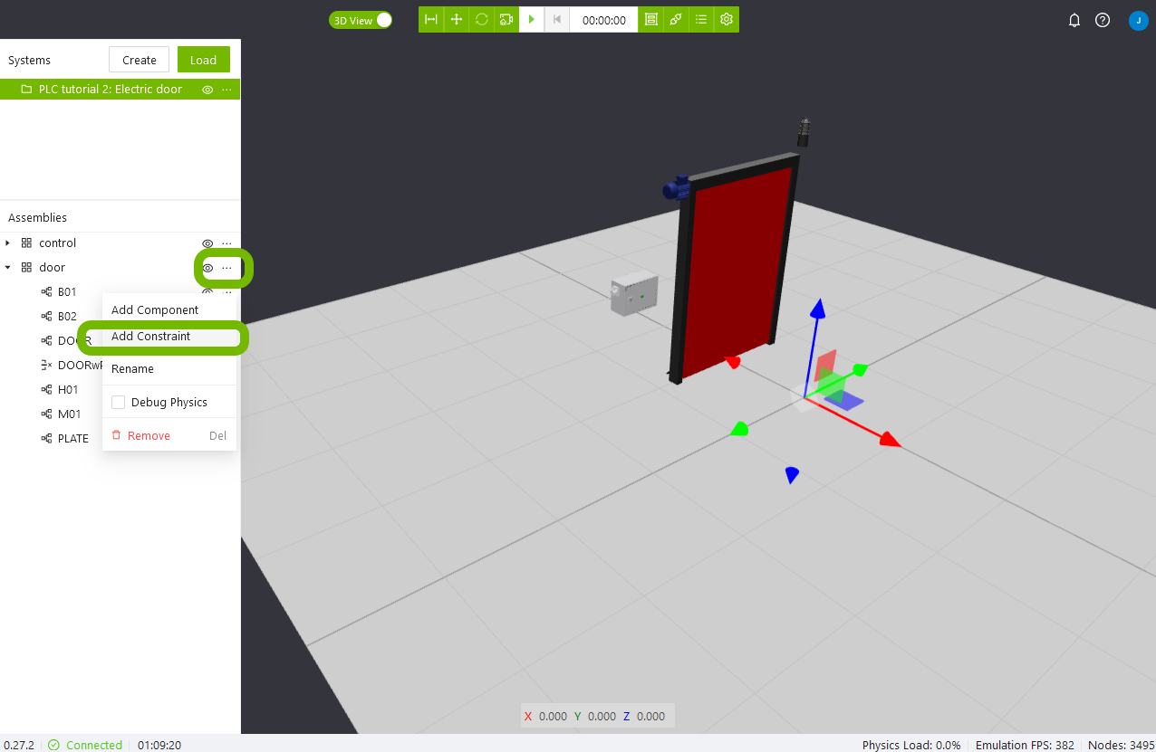
To create a new constraint, click the three dots next to the assembly it should be placed in and select Add Constraint. Select a name for the constraint and press OK.
Properties
This section explains how the properties of a constraint affects the physical connection.
Axis
By default, the axis is 'fixed'. The table below explains how the different values give different degrees of freedom. This can be used when a link is supposed to follow a straight guide rail, or rotate around a hinge for example.
| Value | Definition |
|---|---|
| fixed | No movement is allowed between the parent and child |
| x | The child is allowed to move along its own x axis |
| y | The child is allowed to move along its own y axis |
| z | The child is allowed to move along its own z axis |
| rx | The child is allowed to rotate around its own x axis |
| ry | The child is allowed to rotate around its own y axis |
| rz | The child is allowed to rotate around its own z axis |
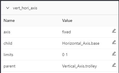
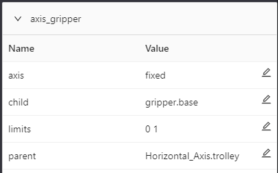
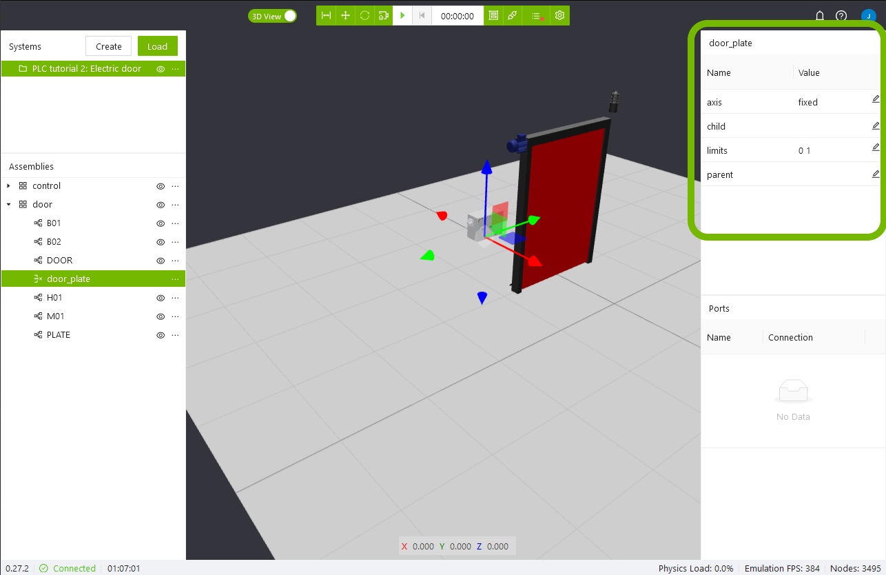
Child
The child element is constrained to the parent, it can be allowed some degree of freedom as specified by the Axis property.
Limits
This property determines how far the child element is allowed to move in the specified degree of freedom. If the Axis is 'fixed' this property does not have any effect. For linear motion the value is defined in metres, while rotational values are in radians.
Parent
This is the element which the child will follow. It can be left empty, in which case the child will be anchored to a fixed position in the world, and only allowed to move as the Axis and Limits properties specify.
Example
In the example below, the base link of the horizontal actuator is fixed to the moving link of the vertical actuator. Also, the gripper is fixed to the moving link of the horizontal actuator.
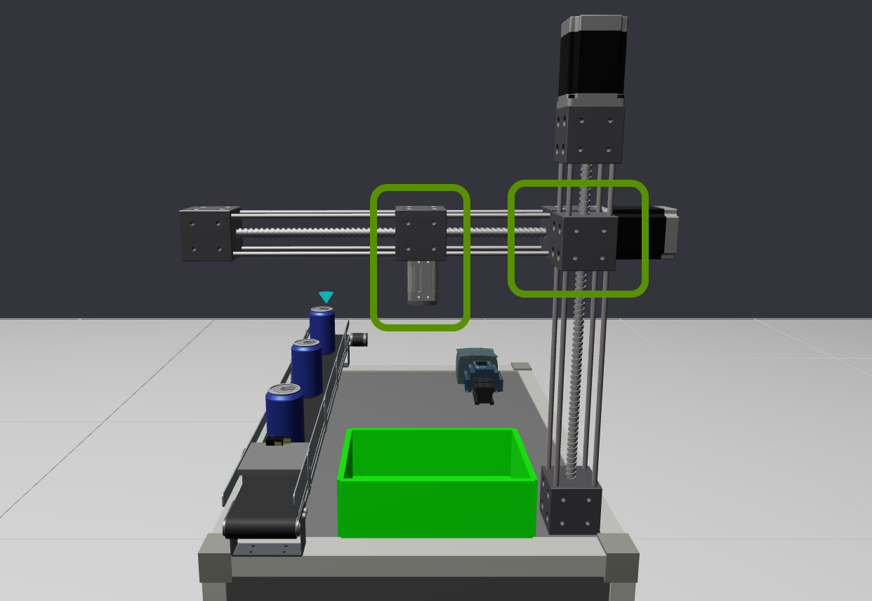
These two constraints are configured as in the images below.