About The Open Emulation Platform
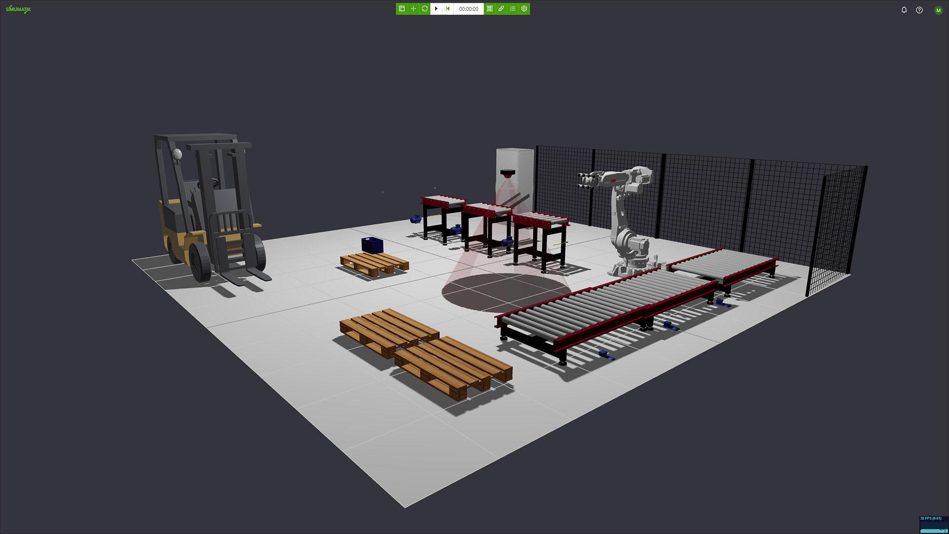
The Simumatik Open Emulation Platform (OEP) provides a flexible digital environment for constructing and exploring physical, electrical, pneumatic and mechatronic systems. The engineer or student is given open ended tools to build and simulate any kind of system. The ability to interface with the world outside the simulation enables the user to program robots and PLC circuits in the virtual world, creating digital twins that then can be transfered to real world systems. This makes it possible to virtually commission systems into production, lowering risk and reducing cost.
Our Platform Architecture
All of this is delivered by our platform architecture. The OEP is divided into:
- Cloud storage: Where all data is stored, such as systems, components, and their assets.
- Emulation server: Where the models are built and executed.
- Web-app client: Used to browse the cloud data, and components, and to interface with the emulation server.
- Gateway service: Used to connect the emulation server with third-party software and hardware.
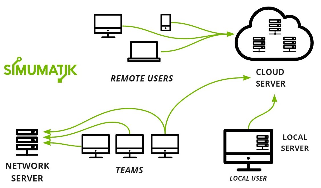
The emulation server can run on a local machine, a machine in a local network, or in the cloud. This gives multiple users the opportunity to collaborate simultaneously in real-time. Running as much as possible in the cloud reduces costs and required computing resources.
The Concept - How It Works
Emulation means that the virtual systems you build will look and behave like their real world counterparts.
- Visuals: How the component or system looks and appears in 3D-space.
- Physics: The physical properties of a component, including material, collision shape and kinematics. All used to replicate physical interaction using a physics engine.
- Interface: The connection points points of a component, allowing it to be connected to other components or third party software. These include electric, pneumatic and mechanical ports for example.
- Behavior: Components can be programmed to contain logic, bringing them to life. Component logic is programmed in the Python programming language.
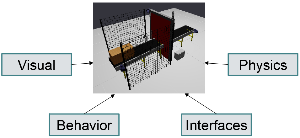
Each aspect, visual, physical, interfaces and behaviour, is flexible and together they allow modeling almost any component you can imagine - from basic products, sensors and motors, to PLCs and robot controllers. However, not every component requires all aspects to be modeled.
A System Hierarchy
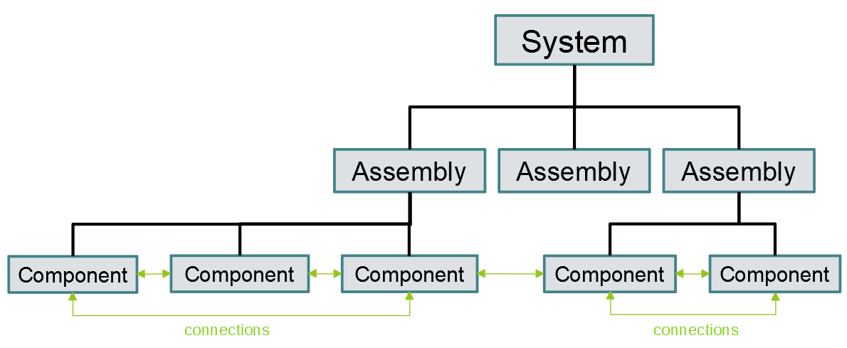
Components are the basic building blocks. When placed together they create an assembly. One or several asseblies makes up a system.
The idea of component-based modeling is simple. Each element in the system with a specific use case is considered a component. Our platform allows users to create these systems and components and share them with other users.
The connection principles
The emulation model follows the same principles that are applied to engineering drawings. In the example below we have three components. A valve, a cylinder and a pump forming a system. The components are connected and the system will behave in a similar way to a pysical system, even when connected incorrectly. This system is very basic, but the ability to detect errors scale to large systems as well, where early discovery of errors may result in large cost savings later in the development process.
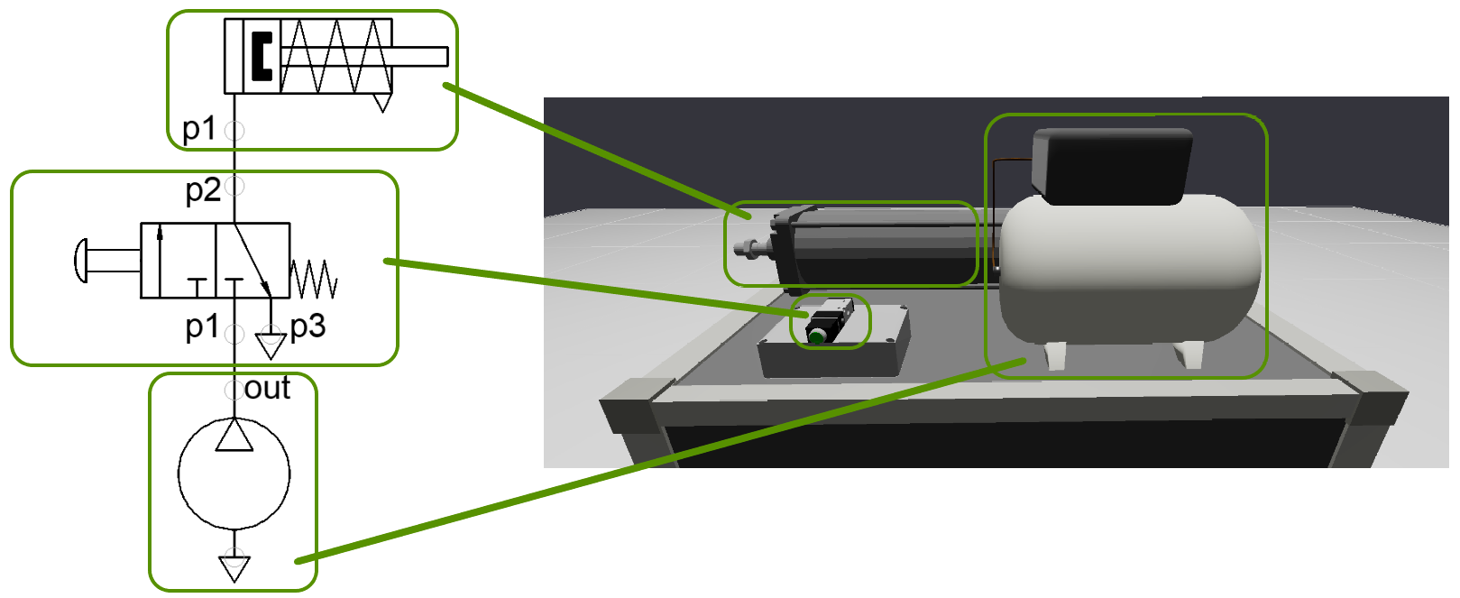
In Simumatik, connections between components are made with the help of ports. Each component can have ports of a certain type (e.g. electric, pneumatic, etc) which can be configured as inputs or outputs.
The rule for making a connection is simple. Two components can be connected if their ports are the same type (e.g. electric) and the connection is made from an output to an input port. Also, one output port can be connected to several input ports.
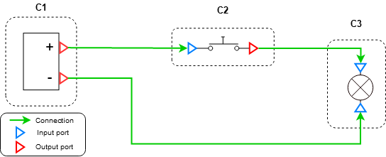
The diagram below shows a basic electric circuit including three components. C1 is a battery connected to C2, a switch, which is connected to C3, a light led. C3 is finally connected back to the negative pole of the battery. The electricity will flow when C2 is pressed, causing the light to turn on.
Why input and output ports?
In the real world, there is no such thing as electric input or output ports in components. Component ports are just connected to each other and the results obtained from the system depend on the total interaction between all ports. This requires seeing the system as an entity, which in mathematics requires generating complex differential equations to simulate the system. Because Simumatik uses a component-based approach we found a way to simplify this problem by forcing ports to be inputs or outputs. This way, the system is emulated, running each component separately.
Ports in Simumatik have at least two variables of two different types:
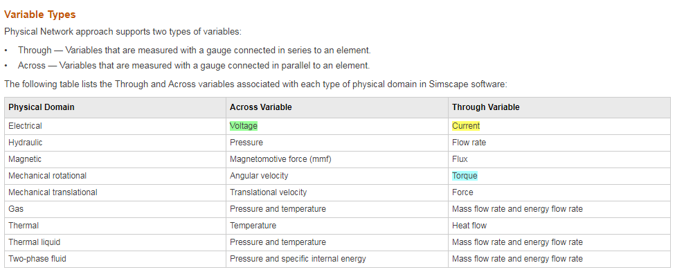
The Across variables are the ones that are set from the output in the inputs (i.e. voltage), while the through variables are the ones set by the inputs to the outputs (i.e. current). Like in the example above, a power supply will have two outputs setting respectively 24V and 0V, while a lamp will have two inputs. If the lamp gets enough voltage difference between its ports, it will switch on and set some current in both ports.
Third-party software/hardware integration
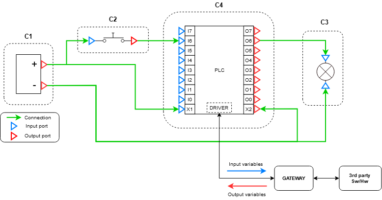
Some components may need to exchange information with other software or hardware, such as a PLC or a robot controller. Therefore, Simumatik has developed the Gateway, a complementary software that acts as an intermediary between the OEP and a third-party platform, such as RobotStudio, RoboDK, Codesys, TIA Portal, etc.
From the user perspective, components can make use of special elements called drivers, which are abstraction layers ready to send and receive variables from the outside. They are in charge of handling the communication, so components can focus on handling the I/O information.
The following diagram shows an electric circuit including four components. The new item introduced in this circuit is C4, a Programmable Logic Controller. A PLC will allow us to control the logic of the whole system by reading its inputs and generate some outputs according to the internal state. In this case, we could enable the O6 output port in order to turn on the light, when it detects a signal in the I6 input port.
Emulation Server
The emulation server is an application that includes different engines (physics, behavior, and interface) in order to run emulation models.
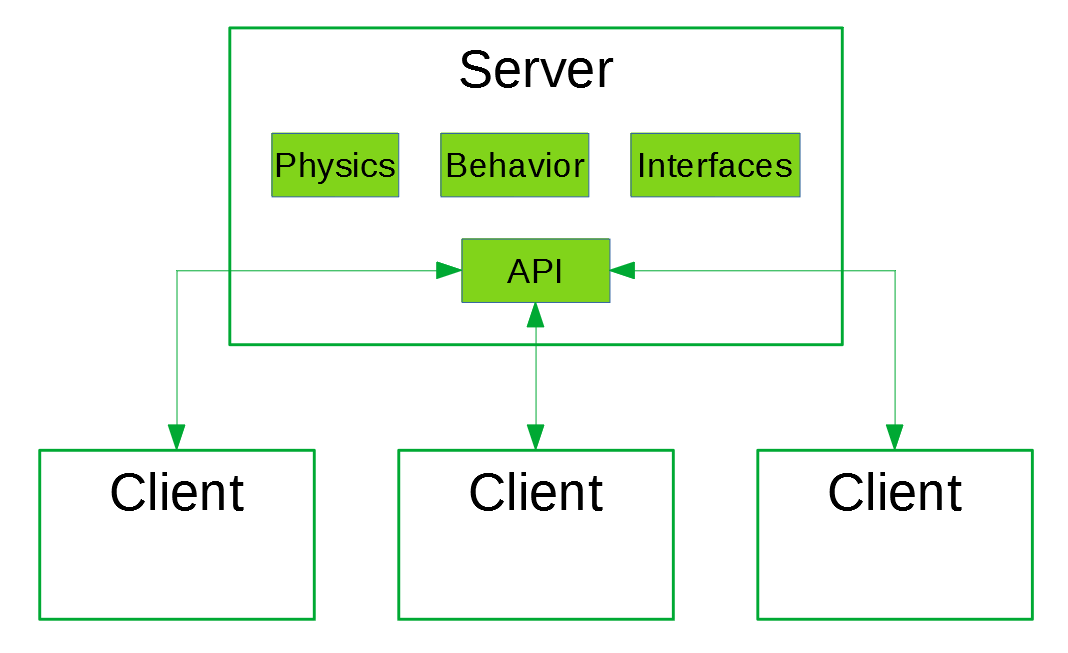
Systems are loaded and stored in the cloud. The execution is performed on a server instance, which may be either cloud based or local. All rendering takes place in the clients, and multiple clients can render the scene independently.
This arquitecture allows more scalability and makes possible to execute complex models even if the user lacks powerful hardware.
Note
The server is a cross-platform application that currently runs on Windows only. The online version of the server is usable on all operating systems with a suitable web browser.