Workspace settings
The workspace setting can be accessed by pressing the rightmost gear icon in the toolbar.
![]()
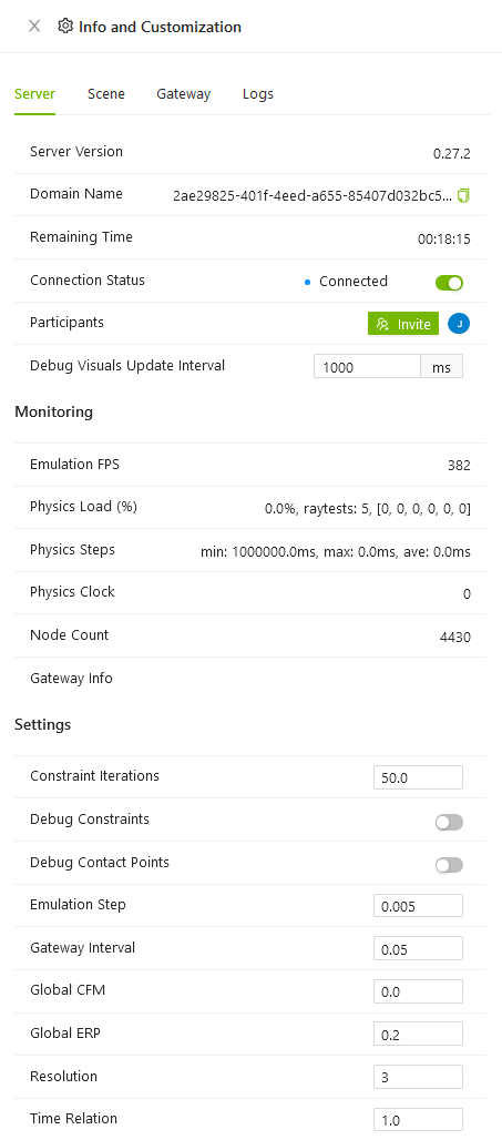
This brings up the following panel. There are 4 different tabs (Server, Scene, Gateway and Logs), the settings for each tab are explained below.
Server settings
In this tab, all settings related to the current server can be configured.
General
Server Version
Displays the version of the connected server.
Domain Name
Displays the domain name of the server.
Remaining Time
Displays how much time is left before the server shuts down (online servers only).
Connection Status
The status is 'Connected' when the app is able to communicate with the server.
Participants
A list of all users currently logged in on the server, the invite button enables to invite other members of the organization to the workspace.
Debug Visuals Update Interval
This setting specifies how frequently the collision visualization is updated when the function is active.
Monitoring
Emulation fps
Displays the update frequency of the physics engine.
Physics Load (%)
Displays how many percent of the emulation step (see description below) that the physics engine requires for each step.
Physics Steps
Displays how long time an emulation step takes to execute. It is important that the physics step is lower than the integration time, otherwise a real-time emulation is not possible.
Physics clock
Displays how long the emulation has been running. It's the same as the server time shown in the toolbar, but with higher resolution.
Node count
Displays how many nodes are currently loaded in the workspace.
Gateway Info
Displays, if the gateway is connected and the emulation is running, how many drivers are connected and how hard the gateway is loaded.
Settings
Constraint iterations
Defines the additional step iterations to carry out on constraint to increase stability.
Debug Constraints
Display physics engine joints and constraints.
Debug Contact Points
Display physics engine contact points. The contact points are visualized as yellow lines to show where collision geometries are touching.
Emulation step
Default is 0.005 seconds. Integration step time used by the physics engine, recommended value between 0.01-0.001.
Gateway interval
Server communication interval in seconds to send UPDATE to the gateway.
Global cfm
If CFM is set to zero (which is the default value), the constraint will be hard. If CFM is set to a positive value, it will be possible to violate the constraint by "pushing on it" (for example, for contact constraints by forcing the two contacting objects together). In other words the constraint will be soft, and the softness will increase as CFM increases. What is actually happening here is that the constraint is allowed to be violated by an amount proportional to CFM times the restoring force that is needed to enforce the constraint. Note that setting CFM to a negative value can have undesirable bad effects, such as instability. Don't do it.
Global erp
The ERP specifies what proportion of the joint error will be fixed during the next simulation step. If ERP=0 then no correcting force is applied and the bodies will eventually drift apart as the simulation proceeds. If ERP=1 then the simulation will attempt to fix all joint error during the next time step. However, setting ERP=1 is not recommended, as the joint error will not be completely fixed due to various internal approximations. A value of ERP=0.1 to 0.8 is recommended (0.2 is the default).
Resolution
Float point resolution for values coming from the physics engine. Value between 3-6. Default 3 (1 mm resolution).
Time relation
Time relation coefficient between emulation time and real time, valid between 0.1-2.0.
Scene settings
In this tab, all settings related to the scene can be configured.
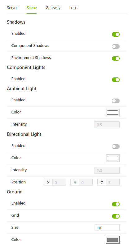
Shadows
Enabled
Determines whether shadows are drawn or not. Having shadows active can have a big impact on performance. It is turned off by default. Remember that component lights only cast shadows if that option has been enabled on the lights themselves, regardless of whether this option is enabled or not.
Component Shadows
Determines whether shadows are drawn on components or not.
Environment Shadows
Determines whether shadows are drawn on the environment or not.
Component Lights
Enabled
Toggles the component lights on or off.
Ambient Light
Enabled
Toggles the ambient light on or off.
Color
Determines the color of the ambient light.
Intensity
Determines the intensity of the ambient light.
Directional Light
Enabled
Toggles the directional light on or off.
Color
Determines the color of the directional light.
Intensity
Determines the intensity of the directional light.
Position
Determines the position of the directional light.
Ground
Enabled
Toggles the ground plane on or off.
Grid
Toggles the grid on the ground plane on or off.
Size
Determines how many squares are distributed along each side of the ground plane. Each square is one square metre.
Color
Determines the color of the ground plane.
Advanced
Shadow Bias
Determines the bias of the shadow map from component lights. This alters how the shadows are calculated, and whether or not a particular object counts as in shadow or not. This value starts with a default of -0.0001. Altering this value may help eliminate shadow artifacts.
Gateway
In this tab, all settings related to the gateway can be configured.
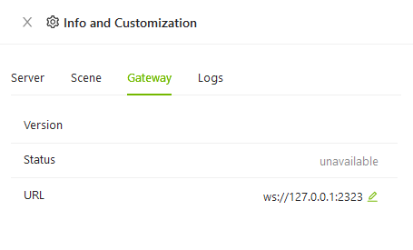
Version
Displays the version of the installed gateway.
Status
Displays the address and connection state of the gateway.
Gateway URL
Sets the URL of the gateway.
Server IP
Sets the IP of the gateway-server.
Export
This tab contains all available options for exporting the workspace scene and components contained within. If you want to limit what systems, assemblies or components are exported, you can simply hide them in the workspace and they will not be included.
Note that the models may be rotated when opened in another program, as not all 3D-modelling software uses the same configuration for the XYZ-axis.
Export Scene (.glb)
Exports the workspace scene to a .glb-file.
Logs
This tab displays log messages sent from the server. Black text is used for INFO messages, while red text is used for ERROR messages. Errors from behavior scripts in components will show up in red text here.
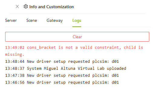
Clear
This button clears all messages from the log.